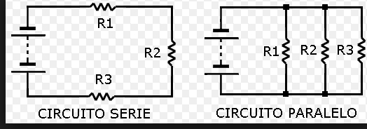
1. Elementos de un circuito eléctrico en serie:
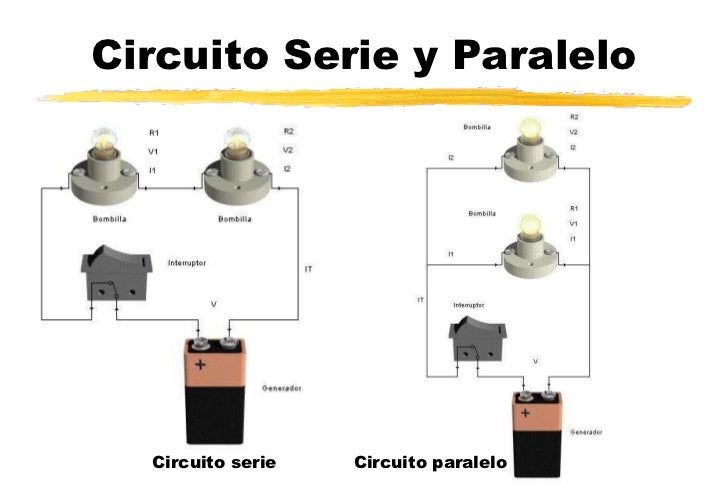
Se denomina circuito eléctrico al conjunto de elementos eléctricos conectados entre sí que permiten generar, transportar y utilizar la energía eléctrica con la finalidad de transformarla en otro tipo de energía como, por ejemplo, energía calorífica (estufa), energía lumínica (bombilla) o energía mecánica (motor). Los elementos utilizados para conseguirlo son los siguientes:
- Generador. Parte del circuito donde se produce la electricidad, manteniendo una diferencia de tensión entre sus extremos.
- Conductor. Hilo por donde circulan los electrones impulsados por el generador.
- Resistencias. Elementos del circuito que se oponen al paso de la corriente eléctrica.
- Interruptor. Elemento que permite abrir o cerrar el paso de la corriente eléctrica. Si el interruptor está abierto no circulan los electrones, y si está cerrado permite su paso.
2. Resistencias de los conductores eléctricos
La resistencia es la oposición que encuentra la corriente eléctrica para pasar por los materiales y esta depende de tres factores:
- El tipo de material. Cada material presenta una resistencia diferente y unas características propias, habiendo materiales más conductores que otros. A esta resistencia se le llama resistividad [ρ] y tiene un valor constante. Se mide [Ω·m].
- La longitud. Cuanto mayor es la longitud del conductor, más resistencia ofrece. Se mide en metros [m].
- La sección. Cuanto más grande es la sección, menos resistencia ofrece el conductor. Por lo tanto, presenta más resistencia un hilo conductor delgado que uno de grueso. Se mide en [m 2].La resistencia de un conductor se cuantifica en ohmios (Ω).
Un circuito en paralelo:
Un circuito en paralelo es un circuito que tiene dos o más caminos independientes desde la fuente de tensión, pasando a través de elementos del circuito hasta regresar nuevamente a la fuente. En este tipo de circuito dos o más elementos están conectados entre el mismo par de nodos, por lo que tendrán la misma tensión. Si se conectan más elementos en paralelo, estos seguirán recibiendo la misma tensión, pero obligaran a la fuente a generar más corriente. Esta es la gran ventaja de los circuitos en paralelo con respecto a los circuitos en serie; si se funde o se retira un elemento, el circuito seguirá operando para el funcionamiento de los demás elementos.
- La tensión es la misma en todos los puntos del circuito.
- A cada uno de los caminos que puede seguir la corriente eléctrica se le denomina "rama".
- La suma de las intensidades de rama es la intensidad total del circuito (IT = I1 + I2 + ... = ΣIi). Donde IT es la intensidad total e Ii son las intensidades de rama.
- La resistencia equivalente es menor que la menor de las resistencias del circuito.
1. Elements of an electrical circuit
It is called electrical circuit into electrical elements connected together to allow the generation, transport and use electric power in order to transform it into another type of energy such as heat energy (stove), light energy (light bulb) or energy mechanical (motor). The elements used to achieve this are:
Generator. Part of the circuit where the electricity is produced, maintaining a voltage difference between its ends.
Driver. Thread along which electrons driven by the generator.
Resistance. Circuit elements that oppose the passage of electric current.
Switch. Element for opening or closing the passage of electric current. If the switch is open not circulate electrons, and if it is closed allows its passage.
2. Resistors electrical conductors
Resistance is the opposition that is the electrical current to pass through the material and this depends on three factors:
The type of material. Each material has a different resistance and its own characteristics, with more conductive materials than others. This resistance is called resistivity [ρ] and has a constant value. [Ω · m] is measured.
The length. The greater the length of the conductor, offers more resistance. It is measured in meters [m].
The section. The larger section is less resistance offered by the driver. Therefore, a thread has more resistance thin conductor thick one. It is measured in [m 2].
The resistance of a conductor is measured in ohms (Ω).
A parallel circuit:
A parallel circuit is a circuit having two or more independent paths from the voltage source, passing through circuit elements to return again to the source. In this type of two or more circuit elements they are connected between the same pair of nodes, so have the same voltage. If more elements are connected in parallel, they will continue to receive the same voltage, but forced to generate more power source. This is the great advantage of circuits in parallel to series circuits; if it melts or element is removed, the circuit will continue to operate for the operation of the other elements.
The tension is the same in all points of the circuit.
Each of the paths that can follow the electric current is called "branch".
The sum of intensities is the total current branch circuit (IT = I1 + I2 + ... = ΣIi). Where IT is the total intensity and Ii are the intensities branch.
The equivalent resistance is smaller than the smallest of the circuit resistors.
No hay comentarios.:
Publicar un comentario